Exclusive terminology for quartz crystals
(1) Nominal Frequency and Tolerance
Under the correct matching of the oscillation circuit, the frequency output from the oscillation circuit is called the "nominal frequency". The frequency unit is generally expressed in megahertz (MHz) or kilohertz (KHz)
In actual mass production and oscillation circuit applications, products will have some frequency dispersion errors relative to the center frequency in room temperature environment (25 ℃) The maximum dispersion value of the allowable error for this type of frequency is generally expressed in ppm (parts per million) or% (percent)
(2) Fundamental and Overtone Vibrations Mode
The quartz crystal resonator at AT cutting angle mainly exists in the thickness shear oscillation mode When a quartz crystal resonates, in addition to the fundamental wave oscillation, higher-order harmonic resonances also coexist with the fundamental wave oscillation between the electrode regions of the quartz crystal However, due to the fact that the electrodes of piezoelectric materials are in an electrically opposite vibration environment, only odd number high-frequency harmonics can occur, and even number harmonic resonances do not exist in quartz crystal resonators
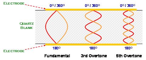
Only odd number harmonic vibrations can be excited in crystal resonator
(3) Load Capacity (CL)
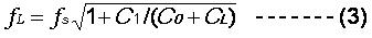
The "load capacitance" on an oscillating circuit is defined as all the capacitance values encountered by the oscillating circuit when viewed from the two terminals of a quartz crystal resonator The load capacitor can be connected in parallel or series with the quartz crystal resonator on the line In oscillating circuits connected in parallel, the size of the load capacitance (CL) will affect the characteristics of the nominal frequency
The resonance frequency of this load capacitor parallel circuit is represented by fL:
(4) Frequency Temperature Stability
The frequency of quartz changes with temperature, which is due to the different coefficients of thermal expansion of quartz material in each axis. When the temperature changes, the lattice spacing in each axis changes slightly When different cutting angles are used, the changes in different oscillation modes will also be different
The design of thickness shear oscillation mode with AT cutting angle is generally defined by using the frequency of 25 degrees Celsius as the reference temperature point to determine the stability of frequency variation within the working environment temperature range While defining the temperature stability parameter for this frequency, the corresponding operating temperature range should also be specified
The frequency stability characteristics of quartz frequency components, similar to the nominal frequency error, are measured in ppm or% The frequency temperature characteristic curve of the component is closely related to the cutting angle, oscillation mode, surface treatment, and external dimensions of quartz In addition, the characteristics of the load capacitance (CL) and drive level on the oscillating circuit also affect the stability of the output frequency of the oscillating circuit with temperature changes
(5) Equivalent Series Resistance (ESR)
When the quartz crystal oscillates in series at fs, C1 and L1 are in opposite phases and cancel each other out. The admittance of the dynamic arm of the entire resonator is close to the minimum impedance value R1. At this point, the performance of the entire quartz crystal resonator is only a resistive element The resistance value R1 is the mechanical energy loss of the entire component This includes quartz material, followed by all energy losses on materials and packaging materials
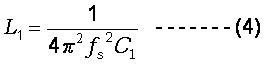
(6) Dynamic capacitance C1 and dynamic inductance L1
In Formula 1, the dynamic capacitance C1 and dynamic inductance L1 are interrelated with the series resonance frequency fs
In actual measurement systems, we can only measure the dynamic capacitance C1 and the series resonant frequency fs. The dynamic inductance L1 is calculated by formula (4)
(7) Static Capacity or Shunt Capacity (Co)
Static capacitance, Co, Mainly derived from the capacitance formed by a quartz chip as the dielectric material and two electrodes; Another small portion of static capacitance comes from the capacitance between the conductive bonding material connecting the quartz chip and the wiring, as well as the capacitance of the packaging shell
Static capacitance is measured in a range far below the oscillation frequency to avoid the influence of dynamic capacitance near the oscillation frequency Formula (5) is the mathematical expression for static capacitance
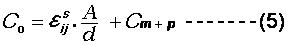
In formula (5), A represents the area of the electrode; D represents the thickness of the quartz chip; ε is the corresponding dielectric value of quartz chips; Cm+p is the capacitance value generated by other materials
(8) Drive Level
The driving power of quartz crystal refers to the power consumption of quartz crystal resonator Usually expressed in microwatts The design of oscillating circuits must provide appropriate power to enable the quartz crystal resonator to start oscillating and maintain oscillation The oscillation of quartz crystal belongs to high-frequency mechanical vibration in physics, and the electrical impedance value during oscillation is about 10-100 ohms or less (depending on the frequency range and size) If the oscillation circuit provides excessive driving power, it will cause changes in the nonlinear characteristics of the quartz crystal and deterioration of the interface between quartz/electrode/bonding material, resulting in excessive changes in the oscillation frequency FL and equivalent impedance R1 Quartz crystals may experience instability when operated under prolonged high driving power With the low power consumption demand of various applications and the trend of product miniaturization, coupled with the significant improvement of quartz product technology in recent years, the overall electrical impedance value of quartz crystal resonators has decreased and remained stable The design of oscillation circuits does not require or should not provide excessive driving energy on quartz crystal resonators For the vast majority of applications, an oscillating circuit providing a maximum power of 10-100 microwatts (depending on the size and frequency of the quartz resonator) is sufficient for the quartz resonator
(9) Electrical Quality Factor (Q)
For quartz crystal resonators, the electrical quality factor Q is an important characteristic The electrical quality factor can be represented by the following formula (6)
The quality factor of the resonator of quartz crystal can reach several million or more
(10) Pullability and Trim Sensitivity
The application of quartz crystal resonators in parallel oscillation circuits is closely related to the oscillation frequency and load capacitance CL This can be seen in formula (3) earlier The following figure is a schematic diagram of the variation curve of load capacitance CL with FL frequency on a parallel oscillation line
The "traction rate" of frequency refers to the frequency variation from the frequency FL1 of load capacitor CL1 to the frequency FL2 of load capacitor CL2 In Figure 11, it can be the frequency variation values of FL1 (CL=24pF) and FL2 (CL=10pF) In this example, the frequency traction rate is 220 ppm. If we minimize the load capacitance values of CL1 and CL2 (by differentiating the curves mathematically), we will obtain the tangent value of the curves This tangent value is the threshold sensitivity of a certain load capacitor
In the figure below, the frequency sensitivity is 10 ppm/pF when CL=24 pF, and 20 ppm/pF when CL=10 pF. In parallel circuits, the smaller the load capacitance, the higher the sensitivity of frequency to changes in load capacitance On the contrary, the larger the load capacitance, the lower the sensitivity of frequency to changes in load capacitance When quartz crystal resonators are used in VCXO circuits, smaller load capacitors are selected in the circuit design On the contrary, when more accurate frequency signals are required, higher load capacitors will be selected in the circuit design
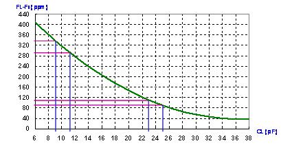
Frequency variation vs. load capacitance
(11) Aging (Aging)
Aging "refers to the frequency variation of quartz crystal resonators over time within a specific time range, expressed in parts per million (ppm) The characteristic curve of aging in frequency and time generally presents exponential changes The period of maximum frequency aging variation occurs in the first month after the quartz frequency element is made Afterwards, the frequency change gradually decreases over time The aging characteristics of frequency are influenced by several main factors For example, the packaging method, type of material, process temperature, process control, heat treatment process, and the size and frequency of the product Most specifications need to define short-term (1-3 months) or long-term (1-10 years) frequency aging requirements
(12) Storage Temperature Range
In addition to the temperature range in the previous working environment, another temperature related characteristic is the "Storage Temperature Range". This parameter refers to the highest and lowest temperature range that the product can store under static conditions Within this temperature range, the product must ensure that it can still operate normally and meet specifications within the working temperature range after long-term storage This characteristic is closely related to the component design and process design of quartz crystal resonators, and should be defined carefully
(13) Negative Resistance (- R)
Negative impedance refers to the impedance characteristic value of the oscillation line at the oscillation frequency when viewed from the two terminals of the quartz crystal resonator towards the oscillation line Sufficient amplification gain value must be provided on the oscillation circuit to compensate for the mechanical energy loss of the quartz crystal resonator during resonance Negative impedance is not a product parameter of quartz oscillators, but an important characteristic parameter of oscillation circuits From the perspective of a resonator, it refers to the "negative impedance" of an oscillating circuit
