PCB testing service
Compatibility between quartz crystal and oscillation circuit
We provide testing board services and will use professional quartz crystal testing equipment to measure the frequency data of individual cells at room temperature and after on board vibration. We will compare and confirm the error between the two to ensure that the frequency error between the customers circuit design and the individual cell is minimized. We will accurately, professionally, and carefully measure the customers circuit board to avoid frequency deviation caused by problems with the application of the customers circuit board and the individual cell.
Step 1: Frequency Accuracy Test:
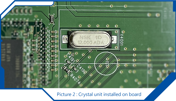
1-1 Obtain data of the quartz crystal body at room temperature using professional testing equipment for quartz crystals
1-2. After mounting the quartz crystal on the board, use Spectrum to measure the frequency of the oscillation on its oscillation circuit
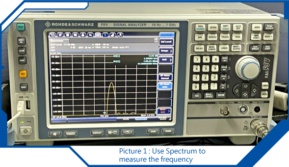
1-3 Compare the data obtained from testing the quartz crystal body with the starting frequency data obtained from the quartz crystal on board to confirm the error between the two
If there is a significant error in the frequency data between the two tests, adjust the load capacitance on the starting line to minimize the frequency data error and avoid frequency offset issues.
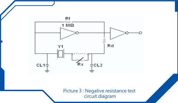
Step 2: - R Test:
2-1 Power on the board, and confirm that Rx value can be confirmed by adjusting Rx so that its quartz crystal can not work normally after confirming that the vibration starts
Insert the Rx value into the formula to calculate the line - R value - R=(R1+Rx)
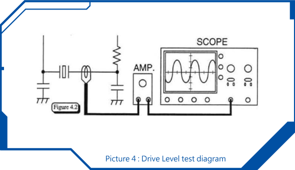
Step 3: Drive Level Test:
3-1 Power on the oscillating circuit and connect it to a current meter. Use professional current testing equipment to obtain the actual current (mA) on the circuit
Apply the current value obtained in 3-2 into the Drive Level formula to calculate its Drive Level value, which is Drive Level=I * RL